Showing posts with label Capacitance. Show all posts

Apr 27, 2022

[paper] Effect of doping on Al2O3/GaN MOS capacitance

B.Rrustemiab, C.Piotrowicza, M-A.Jauda, F.Triozona, W.Vandendaelea, B.Mohamada, R.Gwozieckia, G.Ghibaudob
Effect of doping on Al2O3/GaN MOS capacitance
Solid-State Electronics
Vol. 194, Aug. 2022, 108356
DOI: 10.1016/j.sse.2022.108356
   
a CEA, LETI, Grenoble (Fermi)
b IMEP-LAHC Minatec, Grenoble(FR)


Abstract: This paper investigates the turning-on-voltage (VFB/VTH) of Al2O3/GaN MOS stacks with n-doped GaN, p-doped GaN and not intentionally doped (NID) GaN by exploiting capacitance measurements on large gate area test structures with systematic variation of Al2O3 thickness (tox). Measurements are compared with 1D Schrödinger-Poisson simulations including incomplete ionization model. The necessity of using a quantum description of electron density is demonstrated especially for thinner gate oxides. We found that, contrary to what is expected, p-doping below the channel barely increases the VTH and the VTH is independent of tox, even if the density of activated acceptors is demonstrated to be sufficiently high. Our results highly suggest that the negative charge induced by p-doping is compensated at the oxide level.

Fig: Al2O3/GaN MOS stacks with n-doped GaN, p-doped GaN and its CV plots


Oct 23, 2020

[paper] Capacitive Sensor for Dental Implants

Alireza Hassanzadeh, Ali Moulavi and Amir Panahi
A New Capacitive Sensor for Histomorphometry Evaluation of Dental Implants
in IEEE Sensors Journal, 
DOI: 10.1109/JSEN.2020.3026745

Abstract: Knowing information about the internal functions of the human body has always been the subject of scientific research. Processing of the data from inside of the body gives access to valuable information for the therapist. In this paper, an implantable capacitive sensor has been designed and implemented inside the bone to evaluate the new bone growth. Reducing the medical x-ray imaging dose during a jaw scan is a motivation for the design of the sensor. The new capacitive sensor can replace multiple x-ray imaging sessions. Low energy consumption, stable performance, and information processing rate are some of the engineering challenges for implanted sensors. The designed sensor is a zero power module, which can easily be implemented in dental tooth implants without any active component. The capacitive sensor information can be transmitted to a reader device via a wireless inductive link. The sensor simulation results from a commercial software confirm experimental measurements. The fabricated sensor has been tested on the femur (thigh) bone and mandible bone (lower jaw). The sensor capacitance changes from 20nF to 1.57μF for the fabricated sensor and amount of the surrounding bone. Fabrication results show that variation of sensor capacitance from the early stage of the dental implant to full recovery and bone development is more than seven times. The wide range of sensor capacitance variation allows for better bone development characterization. 

Fig: a) Schematic of a typical sensor and reader inductive link, b) Reader and the implanted sensor.

May 4, 2020

[paper] DHBT with Record ft of 813 GHz

Y. Shiratori, T. Hoshi and H. Matsuzaki,
InGaP/GaAsSb/InGaAsSb/InP Double Heterojunction Bipolar Transistors
With Record ft of 813 GHz
IEEE EDL vol. 41, no. 5, pp. 697-700, May 2020
doi: 10.1109/LED.2020.2982497

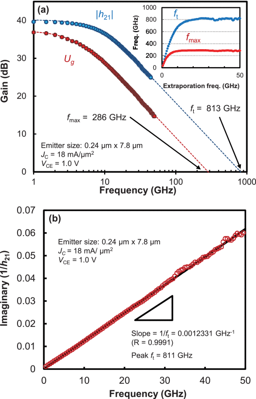
Abstract - We fabricated InGaP/GaAsSb/InGaAsSb/InP double heterojunction bipolar transistors (DHBTs) with an aggressive lateral and vertical scaling technology to improve the current gain cutoff frequency (fT) further. A 13-nm-thick GaAsSb/InGaAsSb base and a 40-nm-thick InP collector are used to reduce electron transit time. In addition, the width of the base electrode on each side of the emitter is reduced to about 0.05µm to suppress increases in parasitic collector capacitance. A fabricated DHBT with the emitter size of 0.24µm×7.8 µm exhibits maximum differential current gain of ∼95 and collector-emitter breakdown voltage of 2.6V. At a collector current density of 18 mA/µm2, the DHBT exhibits fT of 813 GHz, which is the highest among all types of transistors measured at a room temperature.
Fig: (a) Current gain ( |h21| ) and Mason’s unilateral power gain (Ug ) of the DHBT as a function of frequency. JC and VCE are 18 mA/μm2 and 1.0 V, respectively. ft and fmax are extrapolated by single-pole fitting. Inset: frequency dependence of extrapolating ft and fmax . (b) Gummel’s ft extraction (imaginary part of 1/h21 as a function of frequency). The red circles and black line show experimental data and a linear fitting, respectively.

URL: https://ieeexplore.ieee.org/stamp/stamp.jsp?tp=&arnumber=9044299&isnumber=9079222

May 1, 2020

[paper] Physical Mechanisms of Reverse DIBL and NDR in FeFETs With Steep Subthreshold Swing

C. Jin, T. Saraya, T. Hiramoto and M. Kobayashi,
in IEEE J-EDS, vol. 8, pp. 429-434, 2020
doi: 10.1109/JEDS.2020.2986345

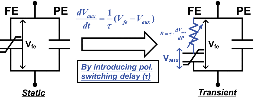
Abstract - We have investigated transient IdVg and IdVd characteristics of ferroelectric field-effect transistor (FeFET) by simulation with ferroelectric model considering polarization switching dynamics. We show transient negative capacitance (TNC) with polarization reversal and depolarization effect can result in sub-60mV/dec subthreshold swing (SS), reverse drain-induced barrier lowering (R-DIBL), and negative differential resistance (NDR) without traversing the quasi-static negative capacitance (QSNC) region of the S-shaped polarization-voltage (PV) predicted by single-domain Landau theory. Moreover, the mechanisms of R-DIBL and NDR based on the TNC theory are discussed in detail. The results demonstrated in this work can be a possible explanation for the mechanism of previously reported negative capacitance field-effect transistor (NCFET) with sub-60mV/dec SS, R-DIBL, and NDR.
Equivalent circuits of a ferroelectric capacitor in both static and transient conditions.

Aug 6, 2015

Best Practices for Compact Modeling in Verilog-A

Mcandrew, C.C.; Coram, G.J.; Gullapalli, K.K.; Jones, J.R.; Nagel, L.; Roy, A.S.; Roychowdhury, J.; Scholten, A.J.; Smit, G.D.J.; Wang, X.; Yoshitomi, S., "Best Practices for Compact Modeling in Verilog-A," Electron Devices Society, IEEE Journal of the , vol.PP, no.99, pp.1,1

doi: 10.1109/JEDS.2015.2455342

Abstract: Verilog-A is the de facto standard language that the semiconductor industry uses to define compact models. Unfortunately, it is easy to write models poorly in Verilog-A, and this can lead to unphysical model behavior, poor convergence, and difficulty in understanding and maintaining model codes. This paper details best practices for writing compact models in Verilog-A, to try to help raise the quality of compact modeling throughout the industry.

keywords: Capacitance, Computational modeling, Convergence, Hardware design languages, Integrated circuit modeling, Mathematical model, Numerical models

[read more...]

REFERENCES[1] S. Liu, K. C. Hsu, and P. Subramaniam, “ADMIT-ADVICE modeling interface tool,” Proc. IEEE Customs Integrated Circuits Conf., pp. 6.6.1- 6.6.4, 1988.
[2] M. Vlach, “Modeling and simulation with Saber,” Proc. 3rd Annual ASIC Seminar and Exhibit, pp. T11.1-T11.9, 1990.
[3] E. McReynolds, personal communication, circa 1995.
[4] E. Christen and K. Bakalar, “VHDL-AMS—A hardware description language for analog and mixed-signal applications,” IEEE Trans. Circuits and Systems II, vol. 46, no. 10, pp. 1263-1272, Oct. 1999.
[5] [Online]: http://www.accellera.org/downloads/standards/v-ams (accessed June, 2015).
[6] L. Lemaitre, G. Coram, C. McAndrew, and K. Kundert, “Extensions to Verilog-A to support compact device modeling,” Proc. IEEE Behavioral Modeling and Simulation Workshop, pp. 134-138, Oct. 2003.
[7] L. Zhou, B. P. Hu, B. Wan, and C.-J. R. Shi, “Rapid BSIM model implementation with VHDL-AMS/Verilog-AMS and MCAST compact
model compiler,” IEEE Int. SOC Conf., pp. 285-286, Sep. 2003.
[8] G. Coram and M. Ding, “Recent achievements in Verilog-A compact modeling,” MOS-AK Workshop, Dec. 2009.
[9] G. Coram, “How to (and how not to) write a compact model in Verilog- A,” Proc. IEEE Behavioral Modeling a Simulation Workshop, pp. 97-106, Oct. 2004.
[10] G. Coram and C. C. McAndrew, “Verilog-A for compact modeling: best practices for high-quality model authoring,” Workshop on Compact Modeling for RF, Sep. 2005.
[11] G. Coram, “Verilog-A: an introduction for compact modelers,” MOS-AK Workshop, Sep. 2006.
[12] M. Mierzwinski, P. O’Halloran, and B. Troyanovsky, “Developing and releasing compact models using Verilog-A,” MOS-AK Workshop, Dec. 2008.
[13] G. Depeyrot and F. Poullet, “Guidelines for Verilog-A compact model coding,” MOS-AK Workshop, Sep. 2009.
[14] M. Mierzwinski, P. O’Halloran, and B. Troyanovsky, “Practical considerations for developing, debugging, and releasing Verilog-A models,” MOS-AK Workshop, Dec. 2009.
[15] C. C. McAndrew and G. Coram, “General and junction primitives for Verilog-A compact models,” nanoHUB. doi:10.4231/D3G15TC2J, 2015.
[16] C. C. McAndrew, “R3,” nanoHUB. doi:10.4231/D3QB9V64G, 2014.
[17] L. W. Nagel, SPICE2: A Computer Program to Simulate Semiconductor Circuits, Memo. ERL-M520, Univ. California, Berkeley, May 1975.
[18] X. Li, W. Wu, G. Gildenblat, C. C. McAndrew, and A. J. Scholten, “Benchmark tests for MOSFET compact models,” in Compact Modeling: Principles, Techniques and Applications, G. Gildenblat (Ed), Springer, pp. 75-104, 2010
[19] Y. Tsividis and C. McAndrew, Operation and Modeling of the MOS Transistor, 3rd ed., New York: Oxford University Press, 2011.
[20] [Online]: http://physics.nist.gov/cuu/Constants/Citations/Search.html (accessed June, 2015)
[21] A. Parker, “Getting to the heart of the matter,” IEEE Microwave Magazine, vol. 16, no. 3, pp. 76-86, Apr. 2015. [22] H. K. Dirks, Kapazit¨atskoeffizienten nichtlinearer dissipativer Systeme, Habilitation Theses, RWTH Aachen University, 1998.
[23] A. C. T. Aarts, R. van der Hout, J. C. J. Paasschens, A. J. Scholten, M. B. Willemsen, and D. B. M. Klaassen, “New fundamental insights into capacitance modeling of laterally nonuniform MOS devices,” IEEE Trans. Electron Dev., vol. 53, no. 2, pp. 270-278, Feb. 2006.
[24] C. C. McAndrew, “Practical modeling for circuit simulation,” IEEE J. Solid-State Circuits, vol. 33, no. 3, pp. 439-448, Mar. 1998.
[25] C. C. McAndrew, “Useful numerical techniques for compact modeling,” Proc. IEEE ICMTS, pp. 121-126, Apr. 2002. [26] K. Kundert, “Hidden state in SpectreRF,” [Online]: http://http://www.designers-guide.org/analysis/hidden-state.pdf (accessed June, 2015)
[27] R. K. Johnson, The Elements of MATLAB R⃝ Style, Cambridge University Press, 2011.
[28] M. Driessen and D. B. M. Klaassen, personal communication, 2006.
[29] [Online]: https://nanohub.org/groups/needs (accessed June, 2015)
[30] L. Lemaitre, C. C. McAndrew, and S. Hamm, “ADMS-automated device model synthesizer,” Proc. IEEE CICC, pp. 27-30, May 2002.
[31] [Online]: http://sourceforge.net/projects/mot-adms/ (accessed June, 2015)